-
Introduction to Project
-
Components used
- Construction of Prototype Design
- Working of Prototype
Project prototype
As we all know that the cost of a petrol and diesel is increasing day by day and the only way to improve an automotive sector without a petrol or diesel fuel is by electrifying the vehicle. We can able to notice that the electric vehicles are growing rapidly all over India from past 3 years, in the majority of Electric vehicles manufacturing now a days are powered using a battery.
Battery is a device that can able to store the specific amount of charge and will discharge it whenever there is a need. The main disadvantages of battery is the less life cycle and slow charging compare to ultra-capacitors or also known as Super-capacitor which acts similar to the battery in majority of characters and hence in our project we are trying to use ultra-capacitors as a secondary power source and it will power the electric vehicle when their is a need of high power during sudden acceleration of electric vehicle. These super-capacitors will be charged using the voltage generated during regeneration braking of the particular electric vehicle Since Super-capacitor are fast charging and contains lakhs together of charging cycles hence they looks quite better than a battery.
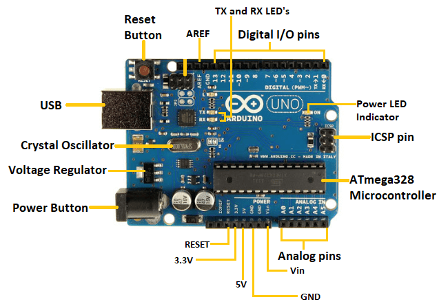
Arduino UNO microcontroller
Arduino UNO is a low-cost, flexible, and easy-to-use programmable open-source microcontroller board that can be integrated into a variety of electronic projects. This board can be interfaced with other Arduino boards, Arduino shields, Raspberry Pi boards and can control relays, LEDs, servos, and motors
In our project the main role of arduino is to control the power shift between battery and motor to super-capacitor and motor by sensing the signals by the transducers
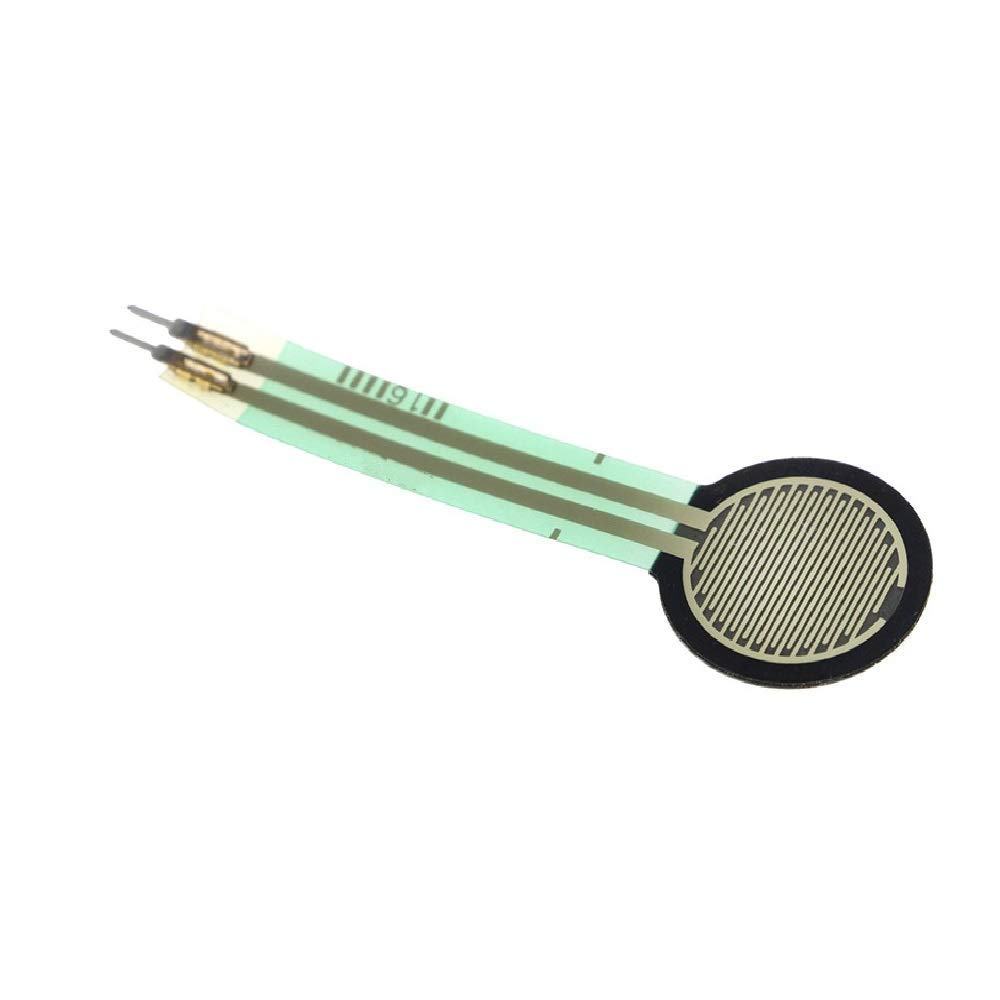
Force Sensitive Resistor (FSR) or Force sensor
A force sensitive resistor (FSR) is a material which changes its resistance when a force or pressure is applied. Conductive film is an example of such force resistance material. In other words, force sensitive resistor it's a sensor that allow you to detect physical pressure, squeezing and weight.
Here we are using the force sensor to detect or sense the external force applied on both accelerator and brake pedal of an electric vehicle.

Lithium-polymer battery
Lithium-polymer batteries are lighter and more flexible than other kinds of lithium-ion batteries because of their soft shells, allowing them to be used in mobile and other electronic devices, as well as in remote control vehicles.The main role of any battery is to power the electrical vehicles.
In our project the lithium-polymer battey acts as a primary power source to drive a motor to give mobility for an electric vehicle
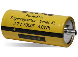
Super-Capacitor or Ultra-Capacitor
Supercapacitors or Ultra-capacitors are excellent energy storage devices and are considered as replacement of Li-ion batteries. The high power density and the fast charging–discharging ability of supercapacitors have made it more attractive toward many industries, such as automobiles, aerospace, and telecommunication etc.
Here Ultra-capacitors are used as a secondary power source in replacement of a lithium polymer battery during heavy load or high power consumption.
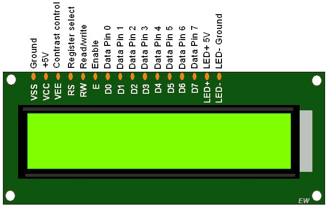
16x2 Liquid crystal Display (LCD)
A 16x2 LCD display is very basic module and is very commonly used in various devices and circuits. A 16x2 LCD means it can display 16 characters per line and there are 2 such lines. In this LCD each character is displayed in 5x7 pixel matrix.
This display is used in our project to show the operating temperature and also the different stages of operation of our project.
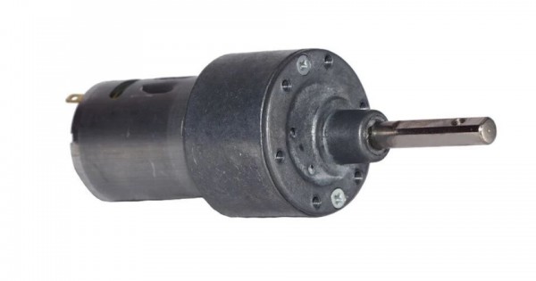
12 V Geared Motor
An electric motor is a device used to convert electrical energy into mechanical energy. Scientifically speaking, the electric motor is a unit used to convert electric power into motive energy or electrical energy into mechanical energy.
The major role of Gearmoter in our project is to drive the wheels to give mobility to a vehicle, it acts like a driver as similar to IC-engines in Petrol vehicles.
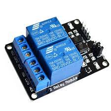
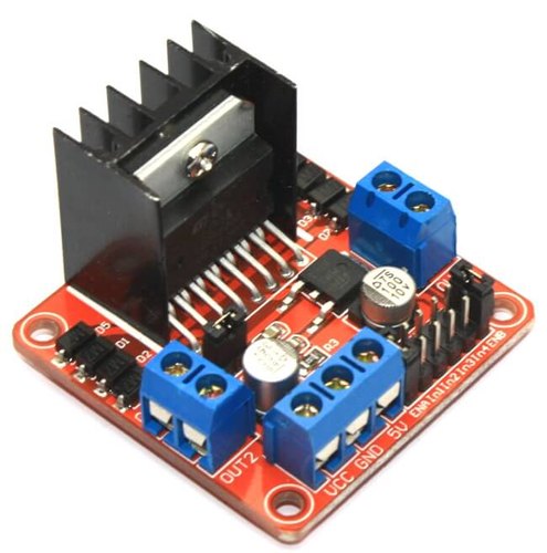
Duel Channel Relay
2-Channel 5V Relay Module is a relay interface board, it can be controlled directly by a wide range of microcontrollers such as Arduino, AVR, PIC, ARM and so on. It uses a low level triggered control signal (3.3-5VDC) to control the relay. Triggering the relay operates the normally open or normally closed contacts.
The major role of duel channel relay in our project is to opening and closing the two main power supply circuits with the help of triggered electrical impulses produced by arduino when their is a need
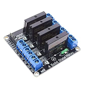
4 Channel Solid State Relay (SSR)
A solid state relay (SSR) is an electronic switching device that switches on or off when an external voltage (AC or DC) is applied across its control terminals. They serve the same function as an electromechanical relay, but as solid-state electronics contain no moving parts and have a longer operational lifetime.
Pulse Width Modulation Driver
The pulse width modulation technique is used in telecommunication for encoding purposes. The PWM helps in voltage regulation and therefore is used to control the speed of motors. In our project the main intension of using PWM driver is to drive accelerate the motor.
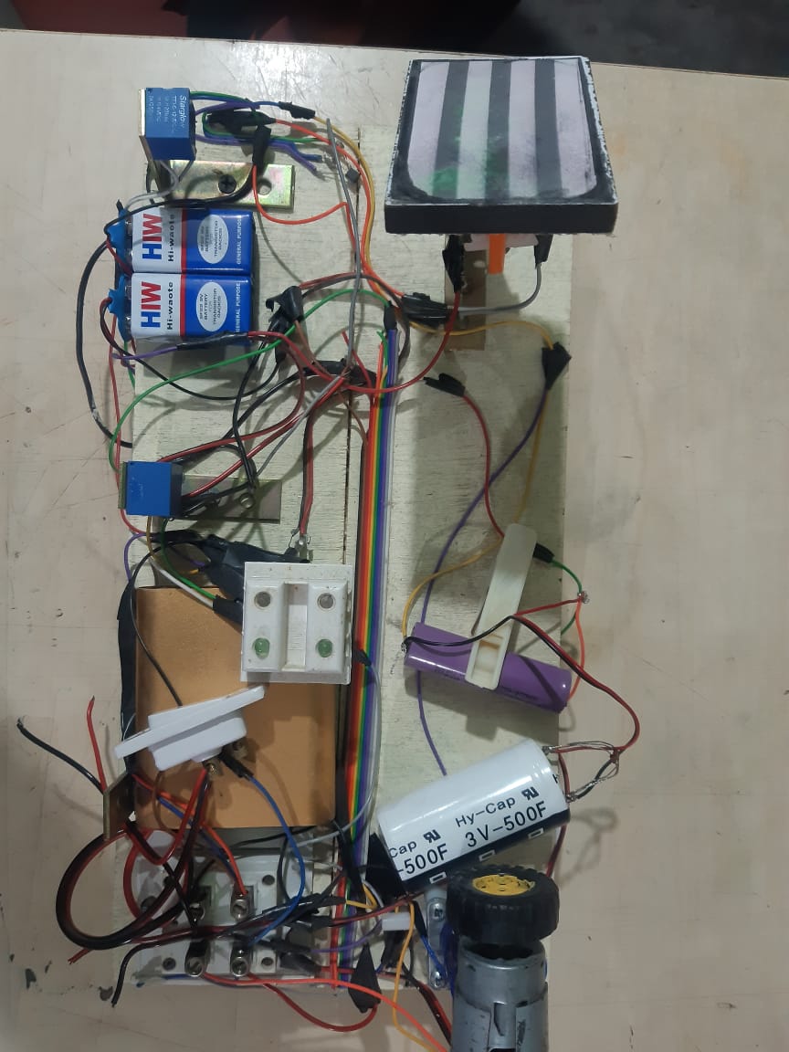
First Design of our Prototype
This is our first design developed mechanically using 2 relays, Battery, LDR sensor and supercapacitor. Their is no usage of microcontroller in our primary design due to which we had only 2 stages of braking and acceleration, this is one of the major drawback of our first design. To overcome from this drawback we decided use a micro controller to achieve complete control on sensors battery,supercapacitors and motor.
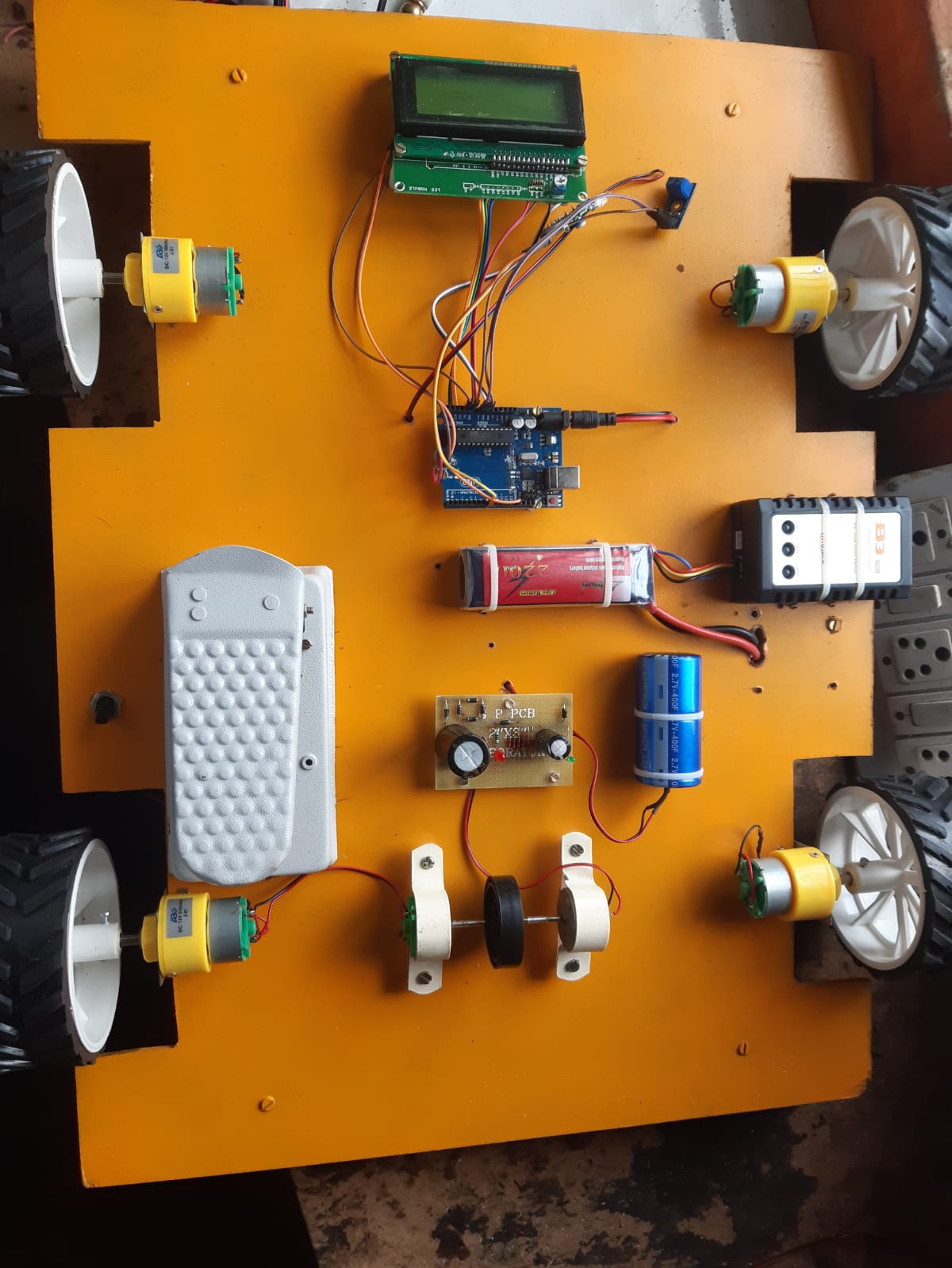
Second Design of our Prototype
We modified our first design by implementing microcontroller to controll the battery and
Supercapacitors power supply with help of input impulses of the sensors, for better
performance we used Force Sensors (FSR) to intake the applied force reading on accelerator and brake pedal.
The main reason why our second design is failed is due to usage of unefficient motor for regeneration.
we were failed to regenerate the required voltage with a normal DC motor with 12v and 1 amp specifications.
And hence we decided to change our complete prototype design.
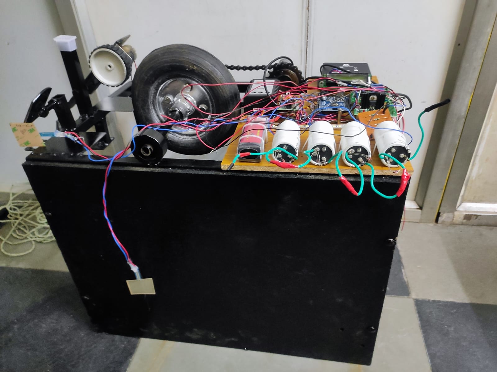
Final Design of our Prototype
The main reason why our second design is failed is due to usage of unefficient motor for regeneration.
we were failed to regenerate the required voltage with a normal DC motor with 12v and 1 amp specifications.
And hence we decided to change our complete prototype design by using two motors one is for driving
a wheel another one is for a regeneration purpose finally we achieved the result with third design.
Working video of prototype
Parts specification
1. 12v 2200mah Li-po battery with adopter
2. 12v 500f Supercapacitor
3. FSR (force sensing resister) sensor
4. 12v relay unit
5. Solid state relay (SSR)
6. Supercapacitor floe controller
7. 2/16 LCSD display
8. Flywheel
9. 12v 500rpm Dc motor for propulsion
10. 12v 100rpm Dc motor for regeneration
11. Sprockets, chain, shafts, frame
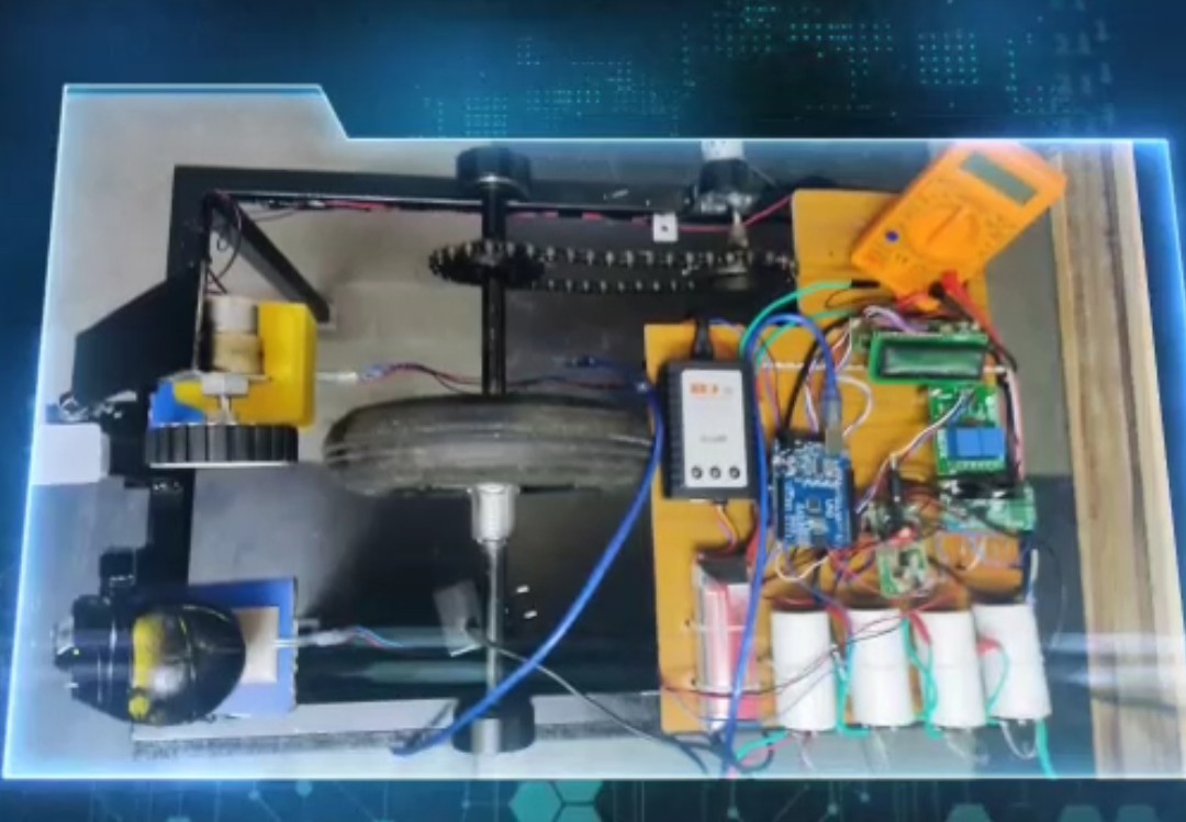
This was our final prototype shown above the system was totally controlled by the help of adrduino microcontroller
which senses with help of FSR sensor the microcontroller is connected with both sources supercapacitor and Li-po
battery and also with the inputs of motors one is of system propel and other is of regeneration and a unit of relay f
or switching purpose are connected to microcontroller the system has 2/16 characteristics LCD display for the
indication of the stages and shifting parameters indication the system is connected to mustimeter to display the
regeneration voltage there is a supercapacitor flow regulator to control heavy voltages in the circuit and the system
is connected to the SSR unit which shown the voltage high low in the form of the illumination of the light.
Classification of the Working
1. Acceleration
Normal Acceleration
High Acceleration
2. Braking
Normal Braking (Regen Stage 1)
Heavy Braking (Regen Stage 2)
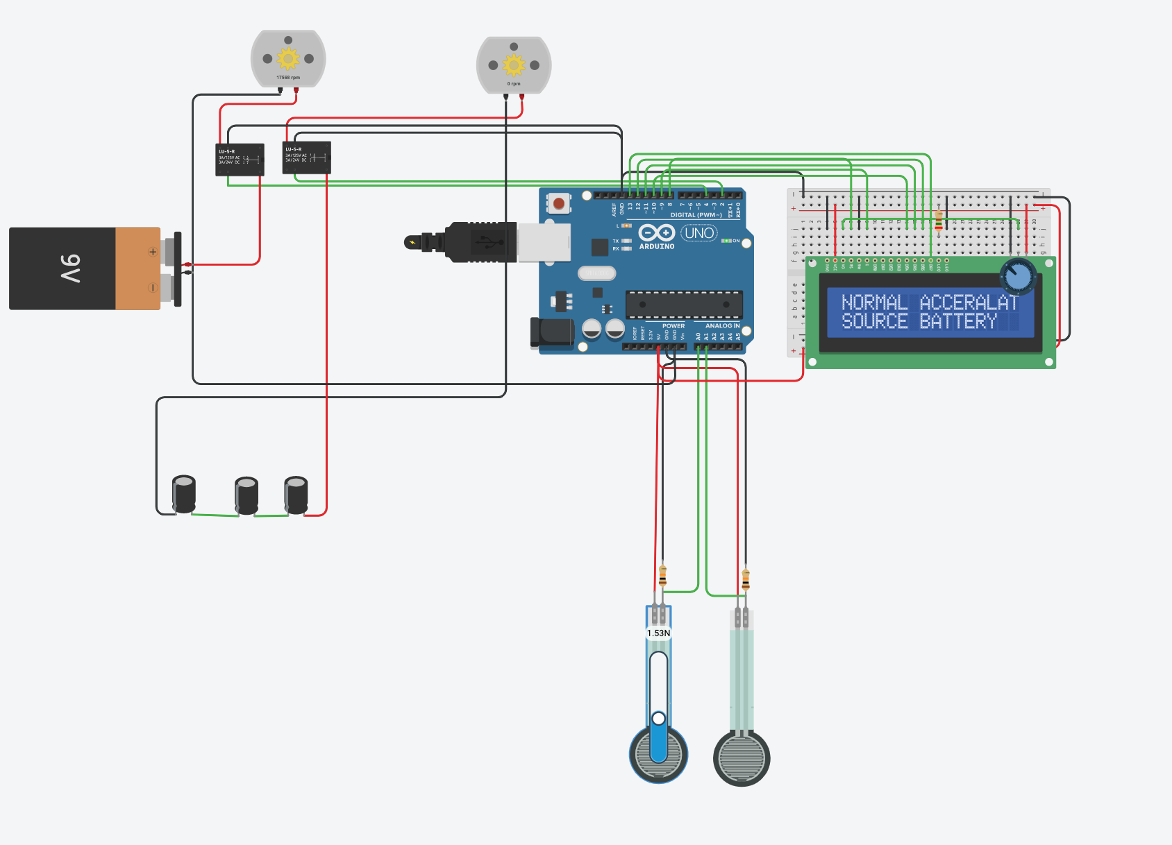
Normal Acceleration stage
In the above image the sensor FSR is connected to microcontroller senses the pressor of the accelerator pedal which is being operated by the driver when the pressure reaches to the pre-registered feed in the microcontroller the shifting takes place as of the working of normal acceleration when driver pressure is light and meets the system registered feed than the microcontroller considers as normal acceleration and the power source is Li-po Battery.

Heavy Acceleration stage
In this working mode the pressure threshold is higher then the normal acceleration when the driver feed on the accelerator is more than the normal accelewration the system considers as heavy accekeration during this condistion the FSR sensor sends the signal to microcontroller where microcontrokller matches with register data and itf its is matching the data it shift ther source batter to supercapacitor as the power flow diagram shown in the above figure.

Normal Braking stage
The mode is truly related to braking and regeneration in this mode while braking the sensing unit under brake pedal which is FSR which senses the data in the form of pressure when the brake reaches to the registered data ,the microcontroller enables the flow of regeneration power from generation motor to supertcapacitor which charges the supercapacitor but due to normal braking the voltage is low compaired to heavy braking the flow of regenerative energy as shown in the above figure.
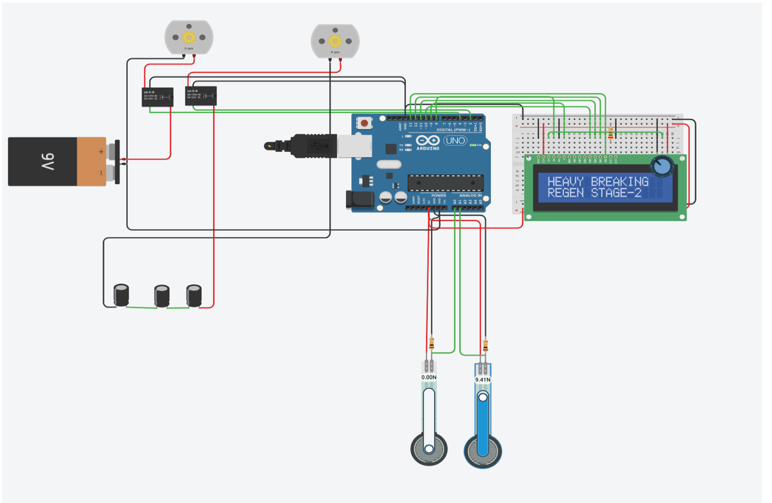
Heavy Braking stage
The pressure threshold value of the FSR sensor is high compared to normal braking here in the mode of operation when the brake pedal get feed more than the normal threshpld valure the feed data is sent to fetch in the microcontroller where it mataches with registerd data if it matches it allows the flow of energy from r egeneration motor to supercapacitor where the energy generated during noraml braking which is regen stage 1 is higher in the haevy braking regen stage 2 mode.